What Is a Valve Seal and How Does It Work?
A Valve Seal is a small engine component with a demanding job. It controls the thin film of oil around each valve stem. This prevents excess oil from entering the combustion chamber. At the same time, it helps maintain proper lubrication between the valve stem and guide. Without that balance, the engine may experience smoke, oil consumption, or uneven performance.
Inside a running engine, temperatures rise sharply around the cylinder head. The seal must remain flexible while resisting heat, pressure, and repeated movement. Most designs use rubber-like materials supported by a metal shell or spring. The valve stem moves through the seal thousands of times per minute. The seal’s lip follows this movement and limits oil migration. Small details matter here. Material quality, installation accuracy, and valve-guide condition can all affect its service life.
Blue smoke after startup may suggest worn valve seals, especially after the vehicle has been parked. However, that symptom does not prove the seals are faulty. Worn piston rings, a blocked ventilation system, or damaged guides can create similar signs. Careful diagnosis is essential. A qualified technician may inspect oil consumption, compression, exhaust behavior, and visible deposits before recommending repairs. In practice, even experienced mechanics can misread early symptoms. That is why understanding how a Valve Seal works provides a useful foundation for reliable maintenance decisions.
What Is a Valve Seal? Definition, Purpose, and Core Components
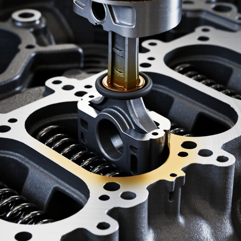
A valve seal is a small sealing component fitted around an engine valve stem. It controls oil flow between the cylinder head and valve guide. The seal allows enough lubrication for smooth valve movement, but prevents excess oil from entering the combustion chamber. Without this balance, the valve may wear quickly, or the engine may burn oil and produce blue exhaust smoke.
Its core components usually include an elastomer sealing lip, a retaining spring, and a metal or reinforced outer shell. The sealing lip contacts the moving valve stem. A tiny spring maintains contact as temperature, pressure, and vibration change. The outer shell holds the seal firmly in its guide position. Materials vary because exhaust valves face intense heat, while intake valves operate under different conditions. It sounds simple. It is not always simple.
During inspection, technicians check hardening, tears, incorrect seating, and valve-stem wear. A new seal cannot correct a damaged guide or a bent valve. Installation also demands care. A sharp valve groove can cut the sealing lip, even when the part looks undamaged. In practical engine repair, clean oil, correct alignment, and the right installation tool matter greatly. I have found that seal failure is sometimes blamed too quickly on poor material. The real cause may be excessive crankcase pressure, blocked ventilation, or an installation mistake. A careful diagnosis should separate these possibilities before replacement.
How Valve Seals Control Leakage at Pressures Exceeding 10,000 psi
What Is a Valve Seal and How Does It Work?
How Valve Seals Control Leakage at Pressures Exceeding 10,000 psi
A valve seal blocks fluid from escaping around the stem, seat, or bonnet joint. At pressures above 10,000 psi, tiny clearances become serious leak paths. The seal works by creating controlled contact between engineered surfaces. Pressure may also energize the seal, pressing it tighter against the sealing area.
API Specification 6A lists 10,000, 15,000, and 20,000 psi working-pressure classes for high-pressure equipment. ISO 10423 provides related design and testing requirements for wellhead and tree equipment. These standards emphasize pressure testing, material control, and traceable inspection records.
A metal-to-metal seat can resist extrusion better than a soft seal under severe loading. However, surface damage, thermal cycling, or poor alignment can still cause leakage. A neat calculation can mislead. Real seals age unevenly.
Tips: Confirm the pressure class before selecting a seal. Check temperature, fluid chemistry, and cycling frequency together. Inspect sealing surfaces under magnification, not only by touch. Replace damaged backup rings and measure extrusion gaps. Document every pressure test against API 6A or ISO 10423 acceptance requirements. Small scratches matter.
How Valve Stem Seals Regulate Lubrication and Gas Flow Step by Step
What Is a Valve Seal and How Does It Work?
How Valve Stem Seals Regulate Lubrication and Gas Flow Step by Step
A valve stem seal sits around the narrow stem of an engine valve. Its job is simple, but its timing matters. It meters a small amount of oil between the stem and valve guide. This film reduces friction during repeated opening and closing. Too much oil can enter the combustion chamber. Too little can cause rapid wear.
During the intake stroke, strong vacuum develops inside the cylinder. That vacuum can pull oil downward along the valve stem. The seal’s flexible lip presses against the moving stem and limits this flow. A small spring often maintains contact as the rubber-like material ages. During compression and combustion, the seal also helps prevent combustion gases from traveling upward into the guide. The result depends on pressure, temperature, stem movement, and oil viscosity.
Exhaust-side seals face intense heat. Their material must remain flexible without becoming brittle. In real workshop inspections, blue exhaust smoke after idling can suggest worn seals, though it is not proof. Worn guides, piston rings, or a blocked ventilation system may create similar symptoms. That distinction matters. A careful technician checks several causes before replacing parts. Seal performance is not perfectly constant. Cold starts, high engine speed, and deposits can change the oil film. Even a new seal may fail if installed crookedly or damaged by the valve stem groove.
Valve Seal Materials and Temperature Ratings Up to 650°C
A valve seal prevents fluid from escaping around moving or joined parts. Stem seals are especially important: they surround the valve stem while allowing controlled movement. Packing rings compress inside the stuffing box. Elastomeric seals are flexible, but heat can harden or swell them. Metal seals tolerate greater heat, though they demand accurate surface finishes and alignment.
Material choice changes sharply near 650°C. PTFE commonly serves near 260°C, while graphite packing can operate around 450°C in steam and approach 650°C in controlled, low-oxygen conditions. The difference matters. Oxidation can destroy graphite faster than temperature charts suggest. Ceramic and metal sealing elements may survive higher temperatures, but thermal expansion can reduce contact pressure during cycling. This is where laboratory ratings become less convincing.
API 622 qualification testing uses methane leakage measurements, 1,510 mechanical cycles, and repeated thermal cycles for packing assemblies. ISO 15848-1 also evaluates fugitive emissions through defined leakage classes and temperature procedures. These standards show that sealing performance is measured, not simply advertised. A 650°C rating should therefore identify the medium, pressure, atmosphere, cycling frequency, and seal geometry. Without those details, the number is incomplete. In field inspections, I would check discoloration, packing compression, stem scoring, and nearby heat shields. Small leakage can grow quickly. One overlooked weakness remains possible.
Common Valve Seal Failures, Industry Test Standards, and Service Limits
A valve seal sits between moving or stationary parts and controls the passage of fluid, gas, or pressure. Its contact lip, packing surface, or elastomer ring must remain flexible under operating conditions. A seal that is too tight may create friction and heat. One that is too loose can permit leakage.
Common failures include hardening, swelling, extrusion, cuts, compression set, and surface wear. Heat accelerates aging, while incompatible fluids can soften or crack the sealing material. Poor shaft finish and misalignment also cause uneven wear. A seal can look fine. It may still leak under pressure. Field inspection should record leakage rate, temperature, pressure, cycle count, and the fluid used. Guesswork often hides the real cause.
Testing normally combines visual inspection, dimensional checks, pressure testing, and material evaluation. ISO 5208 is commonly used for industrial valve pressure and leakage testing. API 598 may apply where its requirements are specified. ASTM methods can help assess tensile strength, compression set, hardness, and fluid resistance. The correct test depends on valve design and service conditions. Service limits should include maximum pressure, temperature range, cycling frequency, fluid compatibility, and allowable leakage. These limits are not permanent truths. Real installations may involve vibration, contamination, or thermal shocks that laboratory tests miss. A practical review should compare test results with actual operating records before approving continued service.