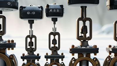
A flow control valve regulates the movement of liquids, gases, or steam through a pipeline. It adjusts flow rate by changing the passage available to the fluid. In a factory, this may mean keeping cooling water steady or limiting steam entering a heat exchanger. Small position changes can affect pressure, temperature, product quality, and energy use. The boundary is not always neat. Valve selection depends on the entire system, not the valve alone.
Industry data shows why this equipment matters. MarketsandMarkets reported that the global industrial valves market was valued at approximately USD 78 billion in 2023 and projected continued growth through 2028. Grand View Research also identifies process industries, including oil and gas, chemicals, water treatment, and power generation, as major demand sectors. These reports describe broad valve markets rather than flow control valves alone, so their figures should not be treated as a perfect segment measurement. That limitation matters.
Inside a typical assembly, an actuator moves a plug, ball, butterfly disc, or diaphragm. A controller compares the measured flow with the target value, then adjusts valve position. A pressure drop develops across the restriction. The relationship is practical, but not always linear. Cavitation, flashing, vibration, fluid viscosity, and incorrect sizing can reduce performance quickly. ISA-75 standards provide recognized methods for control valve terminology, capacity, and testing. This article explains how a flow control valve works, where it is used, and what engineers inspect before installation. Field experience still matters. A clean specification cannot compensate for poor commissioning, unstable pressure, or neglected maintenance.
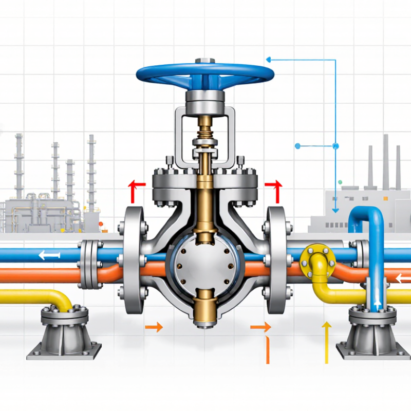
What Is a Flow Control Valve?
A flow control valve regulates how quickly liquid, gas, or steam moves through a pipeline. It works by changing the opening inside the valve. A smaller opening creates greater resistance and reduces flow. A larger opening allows more fluid to pass. The valve may be adjusted manually or operated by an actuator connected to a control system.
In practical installations, technicians select a valve according to fluid type, temperature, pressure, and required flow range. They also check the pipe size and pressure drop. For example, a valve controlling cooling water may respond to temperature changes and maintain steady equipment performance. The pressure gauge should be watched during testing. A sudden rise can indicate blockage, incorrect sizing, or a partially closed downstream valve.
Flow control valves are not simply on-off devices. Their main purpose is controlled movement, not complete isolation. A separate shutoff valve may be needed for maintenance safety. Valve material, seal compatibility, and control accuracy also affect service life. Small details matter.
A common mistake is choosing a valve by pipe diameter alone. That approach can produce unstable flow, noise, vibration, or poor response. Real systems rarely behave perfectly. Fluid properties can change, and sensors may drift over time. For reliable operation, engineers should compare operating data with design requirements and inspect the valve during scheduled maintenance. The best selection is sometimes less obvious than expected.
A flow control valve regulates fluid movement by changing the size of its internal passage. The chart shows calculated water flow at a constant pressure drop of 1 bar for different valve openings, using the standard metric flow coefficient equation: Q = Kv × √(Δp).
As the valve opens, its effective flow coefficient increases, allowing more water to pass through under the same pressure conditions. Actual performance depends on valve geometry, fluid properties, and system pressure.
A flow control valve regulates how much fluid passes through a pipeline. It can slow, stop, or redirect liquid, gas, or steam. Its key components include the valve body, trim, stem, actuator, positioner, and seals. The body contains pressure, while the trim shapes the flow path. The actuator moves the stem after receiving a manual, pneumatic, hydraulic, or electronic signal. A positioner improves accuracy by comparing the desired opening with the actual position.
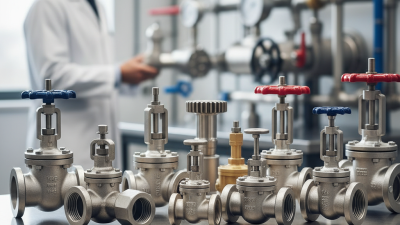
Common types include globe, butterfly, ball, needle, diaphragm, and pinch valves. Globe valves offer precise throttling. Butterfly valves suit large pipes and lower-pressure duties. Ball valves provide fast shutoff, but they are not always ideal for continuous throttling. Needle valves control small flows with fine adjustment.
A 2024 Grand View Research report estimated the global industrial valves market at about 78 billion dollars in 2023, with continued growth through 2030. The figure signals strong demand, but market size does not guarantee correct selection. Poor sizing still creates noise, vibration, and unstable control.
Tips: Check flow rate, pressure drop, temperature, fluid chemistry, and required shutoff performance. Review the valve after installation. The first setting may be wrong. The U.S. Department of Energy reports that compressed-air systems can lose 20–30% of output through leaks and poor maintenance. A correctly selected valve cannot repair an ignored system. Record real operating data, not only design assumptions.
A flow control valve regulates fluid flow by changing the passage available inside a pipe. When the opening narrows, resistance increases and the flow rate usually falls. When it opens wider, more fluid passes through. This simple action supports stable operation in water lines, hydraulic equipment, heating systems, and process piping.
Inside the valve, a plug, needle, disc, or ball moves against the fluid path. In a manual system, an operator adjusts the position using a handle. In an automatic system, an actuator responds to signals from a flow meter, pressure sensor, or temperature controller. The controller compares the measured condition with the required setting, then moves the valve slightly.
Small movements matter.
A practical example is a cooling-water circuit. If heat rises, the control system can open the valve further, allowing more water to reach the equipment. Excessive closure may create noise, vibration, or cavitation when pressure drops too sharply.
That detail is easy to miss.
Pipe size, fluid viscosity, upstream pressure, and valve trim all affect performance. A valve that works well with clean water may respond poorly to dirty or highly viscous fluid.
Technicians should check direction arrows, actuator calibration, and leakage during commissioning. They should also inspect the valve after unusual pressure changes. A flow setting can look correct while the pump operates inefficiently.
This is where assumptions fail.
Good regulation requires measurement, not guesswork.
A flow control valve regulates how quickly liquid or gas moves through a system. Its opening changes the passage size, creating more or less resistance. Operators adjust it manually, electrically, or through a pneumatic actuator. A pressure-compensated design can maintain steadier flow when inlet pressure changes. However, no valve performs perfectly under every condition.
In water treatment plants, these valves control chemical dosing, filter backwash, and discharge lines. A small adjustment can protect pumps and prevent sudden pressure changes. In HVAC systems, they balance chilled-water flow through coils. This helps maintain stable room temperatures and reduces wasted energy. Irrigation systems use them to limit water delivery across different zones. Without careful adjustment, one area may become saturated while another stays dry.
Manufacturing equipment uses flow control valves for cooling, lubrication, and hydraulic movement. Pneumatic systems rely on them to control cylinder speed, such as a clamp closing gently instead of striking hard. Small details matter. Incorrect sizing may cause noise, vibration, or slow response. Dirt, high viscosity, and worn seals can also distort performance. A reliable installation includes a suitable filter, accessible service points, and regular inspection. A clean calculation is useful, but field conditions can still expose assumptions that need review.
A flow control valve regulates fluid movement by changing its internal opening. The actuator responds to a signal, while the valve’s position adjusts flow, pressure, or temperature. Selection should begin with the medium, minimum and maximum flow, operating pressure, temperature, and required Cv. A water valve may fail quickly in abrasive slurry. That detail matters.
Check the valve material, seal compatibility, pressure class, control signal, and fail-safe position. The International Energy Agency reported that industry used about 37% of global final energy in 2022. Small control losses can therefore become expensive across continuous operations. Oversizing is a common mistake. It can cause unstable movement, poor resolution, and unnecessary wear. A precise calculation is better than relying on pipe diameter alone.
Installation should follow the flow arrow and the manufacturer’s straight-run requirements. Flush welding debris before connection. Support the pipeline separately, so its weight does not load the valve body. After installation, test full travel, signal response, shutoff performance, and leakage. Keep records. During maintenance, inspect packing, stems, seats, filters, and actuator air pressure. The U.S. Department of Energy notes that compressed-air systems may lose 20–30% of output through leaks, so a leaking pneumatic actuator deserves attention. Maintenance intervals should follow cycle count and service severity, not only calendar dates. Field conditions are never perfectly predictable. Recheck the assumptions.